- 您现在的位置:买卖IC网 > Sheet目录3891 > PIC16C622A-40/SS (Microchip Technology)IC MCU OTP 2KX14 COMP 20SSOP
43
AT90S1200
0838H–AVR–03/02
Reading the Signature Bytes
The algorithm for reading the signature bytes is as follows (refer to “Programming the
Flash” on page 39 for details on command and address loading):
1.
A: Load Command “0000 1000”.
2.
C: Load Address Low Byte ($00 - $02).
Set OE to “0”, and BS to “0”. The selected signature byte can now be read at DATA.
Set OE to “1”.
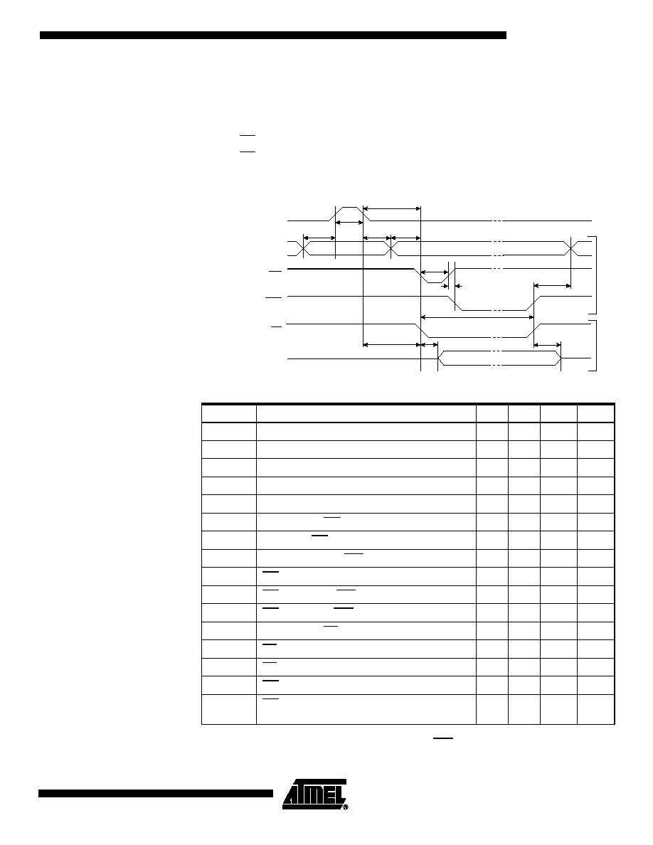
Parallel Programming
Characteristics
Figure 33. Parallel Programming Timing
Notes:
1. Use t
WLWH_CE for chip erase and tWLWH_PFB for programming the Fuse bits.
2. If tWLWH is held longer than tWLRH, no RDY/BSY pulse will be seen.
Table 17. Parallel Programming Characteristics, T
A = 25°C ± 10%, VCC = 5V ± 10%
Symbol
Parameter
Min
Typ
Max
Units
V
PP
Programming Enable Voltage
11.5
12.5
V
I
PP
Programming Enable Current
250.0
A
tDVXH
Data and Control Setup before XTAL1 High
67.0
ns
t
XHXL
XTAL1 Pulse Width High
67.0
ns
t
XLDX
Data and Control Hold after XTAL1 Low
67.0
ns
tXLWL
XTAL1 Low to WR Low
67.0
ns
t
BVWL
BS Valid to WR Low
67.0
ns
t
RHBX
BS Hold after RDY/BSY High
67.0
ns
tWLWH
WR Pulse Width Low
67.0
ns
t
WHRL
WR High to RDY/BSY Low
20.0
ns
t
WLRH
WR Low to RDY/BSY High
0.5
0.7
0.9
ms
tXLOL
XTAL1 Low to OE Low
67.0
ns
t
OLDV
OE Low to DATA Valid
20.0
ns
t
OHDZ
OE High to DATA Tri-stated
20.0
ns
tWLWH_CE
WR Pulse Width Low for Chip Erase
5.0
10.0
15.0
ms
t
WLWH_PFB
WR Pulse Width Low for Programming the Fuse
Bits
1.0
1.5
1.8
ms
Data & Contol
(DATA, XA0/1, BS)
DATA
W
rite
Read
XTAL1
t
XHXL
t
WLWH
t
DVXH
t
XLOL
t
OLDV
t
WHRL
t
WLRH
WR
RDY/BSY
OE
t
XLDX
t
XLWL
t
RHBX
t
OHDZ
t
BVWL
发布紧急采购,3分钟左右您将得到回复。
相关PDF资料
PIC16CE623-30/SO
IC MCU OTP 512X14 EE COMP 18SOIC
PIC16CE624-30/SO
IC MCU OTP 1KX14 EE COMP 18SOIC
PIC16CE624-30/SS
IC MCU OTP 1KX14 EE COMP 20SSOP
PIC16CE623-30/SS
IC MCU OTP 512X14 EE COMP 20SSOP
PIC16CE624-30/P
IC MCU OTP 1KX14 EE COMP 18DIP
PIC16F722-I/SO
IC PIC MCU FLASH 2KX14 28-SOIC
PIC16F677-I/SO
IC PIC MCU FLASH 2KX14 20SOIC
PIC18LC601-I/PT
IC MCU ROMLESS A/D PWM 64TQFP
相关代理商/技术参数
PIC16C622AT-04/SO
功能描述:8位微控制器 -MCU 3.5KB 128 RAM 13 I/O RoHS:否 制造商:Silicon Labs 核心:8051 处理器系列:C8051F39x 数据总线宽度:8 bit 最大时钟频率:50 MHz 程序存储器大小:16 KB 数据 RAM 大小:1 KB 片上 ADC:Yes 工作电源电压:1.8 V to 3.6 V 工作温度范围:- 40 C to + 105 C 封装 / 箱体:QFN-20 安装风格:SMD/SMT
PIC16C622AT-04/SS
功能描述:8位微控制器 -MCU 3.5KB 128 RAM 13 I/O RoHS:否 制造商:Silicon Labs 核心:8051 处理器系列:C8051F39x 数据总线宽度:8 bit 最大时钟频率:50 MHz 程序存储器大小:16 KB 数据 RAM 大小:1 KB 片上 ADC:Yes 工作电源电压:1.8 V to 3.6 V 工作温度范围:- 40 C to + 105 C 封装 / 箱体:QFN-20 安装风格:SMD/SMT
PIC16C622AT-04E/SO
功能描述:8位微控制器 -MCU 3.5KB 128 RAM 13 I/O RoHS:否 制造商:Silicon Labs 核心:8051 处理器系列:C8051F39x 数据总线宽度:8 bit 最大时钟频率:50 MHz 程序存储器大小:16 KB 数据 RAM 大小:1 KB 片上 ADC:Yes 工作电源电压:1.8 V to 3.6 V 工作温度范围:- 40 C to + 105 C 封装 / 箱体:QFN-20 安装风格:SMD/SMT
PIC16C622AT-04E/SS
功能描述:8位微控制器 -MCU 3.5KB 128 RAM 13 I/O RoHS:否 制造商:Silicon Labs 核心:8051 处理器系列:C8051F39x 数据总线宽度:8 bit 最大时钟频率:50 MHz 程序存储器大小:16 KB 数据 RAM 大小:1 KB 片上 ADC:Yes 工作电源电压:1.8 V to 3.6 V 工作温度范围:- 40 C to + 105 C 封装 / 箱体:QFN-20 安装风格:SMD/SMT
PIC16C622AT-04I/SO
功能描述:8位微控制器 -MCU 3.5KB 128 RAM 13 I/O RoHS:否 制造商:Silicon Labs 核心:8051 处理器系列:C8051F39x 数据总线宽度:8 bit 最大时钟频率:50 MHz 程序存储器大小:16 KB 数据 RAM 大小:1 KB 片上 ADC:Yes 工作电源电压:1.8 V to 3.6 V 工作温度范围:- 40 C to + 105 C 封装 / 箱体:QFN-20 安装风格:SMD/SMT
PIC16C622AT-04I/SS
功能描述:8位微控制器 -MCU 3.5KB 128 RAM 13 I/O RoHS:否 制造商:Silicon Labs 核心:8051 处理器系列:C8051F39x 数据总线宽度:8 bit 最大时钟频率:50 MHz 程序存储器大小:16 KB 数据 RAM 大小:1 KB 片上 ADC:Yes 工作电源电压:1.8 V to 3.6 V 工作温度范围:- 40 C to + 105 C 封装 / 箱体:QFN-20 安装风格:SMD/SMT
PIC16C622AT-20/SO
功能描述:8位微控制器 -MCU 3.5KB 128 RAM 13 I/O RoHS:否 制造商:Silicon Labs 核心:8051 处理器系列:C8051F39x 数据总线宽度:8 bit 最大时钟频率:50 MHz 程序存储器大小:16 KB 数据 RAM 大小:1 KB 片上 ADC:Yes 工作电源电压:1.8 V to 3.6 V 工作温度范围:- 40 C to + 105 C 封装 / 箱体:QFN-20 安装风格:SMD/SMT
PIC16C622AT-20/SS
功能描述:8位微控制器 -MCU 3.5KB 128 RAM 13 I/O RoHS:否 制造商:Silicon Labs 核心:8051 处理器系列:C8051F39x 数据总线宽度:8 bit 最大时钟频率:50 MHz 程序存储器大小:16 KB 数据 RAM 大小:1 KB 片上 ADC:Yes 工作电源电压:1.8 V to 3.6 V 工作温度范围:- 40 C to + 105 C 封装 / 箱体:QFN-20 安装风格:SMD/SMT